Configuration of Scenario C
Scenario: A non-supported HQ subsystem must be integrated for the Lite User Interface.
Workflow diagram:
Prerequisites:
- System Manager is in Engineering mode.
- System Browser is in Management View.
Steps:
Creating a Customized Lite User Interface Library
Scenario: You have to create a new library by cloning the structure of an existing one at a lower level. The customized library will be placed at your allowed customization level (for example, L4-Project).
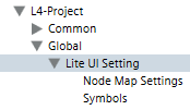
- Select Project > System Settings > Libraries > L1-Headquarter > Global > Lite UI Settings.
- In the Library Configurator tab, click Customize the entire library to a lower level
 .
.
- Click OK.
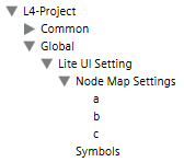
- The structure of the selected library is cloned under the allowed customization level (for example, L4-Project > Global > Lite UI Settings). Only the library structure is recreated here. The blocks in the library are not yet configured.
Creating and Configuring a User Interface
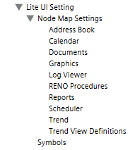
- Select Project > System Settings > Libraries > L4 project > Global > Lite UI Settings > Node Map Settings.
- Select the Library Configurator tab.
- Click New object
 and select New NodeMap Settings.
a. In the New object dialog box, enter a name and description.
b. Click OK.
- In the Extended Operation tab, select the Configuration ID property.
a. Click Modify.
b. In the drop-down-list select the desired Lite User Interface profile.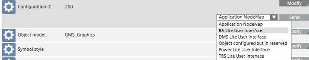
c. Click Send.
- Select the Object Model property.
a. Click Modify.
b. In the text field, enter the desired object model.
Example:
The user can only see the binary schedules. Enter GMS_[desigo_px_EOT_BA_PX_BSCHED_10].
c. Click Send.
- Select the Symbol Style property (not used in Lite User Interface, only for DMS NodeMap).
a. Click Modify.
b. In the text field, enter 2D, 2D+, or 3D as symbol style.
c. Click Send.
- Select the Sort Order property.
a. Click Modify.
b. In the text field, enter a number for the list sequence.
c. Click Send.
- Select the Symbol Reference property.
a. Click Modify.
b. In the text field, enter the graphic symbol reference.
c. Perform the steps in the section Creating Graphic Symbol Reference.
d. Right-click and select Paste.
e. Delete the link prefix [S:Project:].
f. Click Send.
- Select the Include Hidden Alarms property.
a. Select False.
b. Click Modify.
NOTE: This property is not used for building automation, but must be set to False.
- Select the Group ID property.
a. Click Modify.
b. In the text field, enter a number (generally, same as list sequence).
NOTE: This allows grouping several object model types in one section in Lite User Interface (for example, combined analog scheduler, binary scheduler and multistate scheduler).
c. Click Send.
- Select the Group -Text Group ID property.
a. Click Modify.
b. In the text field, enter the name of the text group where the text description is stored (for example, TxG_NodeMap_Groups).
c. Click Send.
- Select the Group - Text ID property.
a. Click Modify.
b. In the text field, enter the index number of the text group name where the text description is stored.
c. Click Send.
- The Lite User Interface is created with the new application.
- In the event additional profiles, for example, GMS_[desigo_px_EOT_BA_PX_MSCHED_10] are required, repeat the workflow as of step 1. The configuration ID is used to assign individual information.
Configuring Lite Users
Scenario: The user operates Desigo CC without the System Browser. The Lite User Interface is activated when changing the client profile.
- Select Project > System Settings > Users.
- Click the Users tab.
- From the Users list, select a user.
- Open the User Settings expander.
- In the Client profile drop-down list, select BA_[xx]_LiteUserInterface.
- Click Save
 .
.
- The user is modified.