3rd Party BACnet Integration
Scenario: You want to configure Desigo CC for connecting to 3rd party BACnet devices. These workflows will guide you through the necessary steps as an online or offline integration.
Reference: For background information on 3rd party BACnet devices, see the reference section.
Workflow diagram:
Prerequisites:
- System Manager is in Engineering mode.
- In System Browser, Management View is selected.
Steps:
This workflow only needs to be executed if no BACnet driver is available for the third-party BACnet network.
Create a BACnet Driver
- The required BACnet driver is not available on the driver list of the server.
- Select Project > Management System > Server > Server > Driver.
- Click New
 , and select the BACnet driver.
- In the New object dialog box, enter a description.
- Click OK.
- The new driver is available in System Browser.
- Select the new driver.
- In the BACnet tab and open the Settings expander.
- In the Management Station section, enter the Instance Number in the BACnet device ID, assigned to the driver as a BACnet client for the BACnet system (for example 34590). This number must be unique on the UDP network.
Start the BACnet Driver
- Select the new driver.
- In the Extended Operation tab, next to the Manager status property, click Start.
- The status of the executed command displays.
Configure the BT BACnet Stack
- Click the BACnet tab.
- Open the BT BACnet Stack Config expander.
- In the BT BACnet Stack Gateway Port Table, click Add and select one of the following:
- To add a Physical Port, select BACnet/IP or Ethernet. In the Port Properties expander, set the Network Number where your management station is connected (typically =1, unless in conflict with the Network Number of the Virtual Port) and select the hardware adapter in the Adapter drop-down list. (For IP address and UDP Port setting of BACnet/IP, see the following guidelines.)
NOTE: To select the network adapter you must start the BACnet driver in full mode. If you are configuring off-line, you need to postpone this step.
- To add a Virtual Port, select Virtual.
NOTE: Any subsequent change in the Network Number field of the Settings expander is automatically reflected in the Network Number field of the Virtual Port.
- (Optional) Configure the Physical Port as BBMD or Foreign Device.
- Click Save
 .
.
- The new driver is available in System Browser.
If you create more than one BACnet Driver, the drivers can be assigned to the same Network Interface Card (NIC) or to different NICs. To avoid configuration conflicts, apply the following guidelines to the Physical Port configuration:
- The Network Number of each Physical Port must be unique.
- The IP Address and UDP Port (default is 47808) of each Physical Port must be unique. This means that the Physical Ports must have a different IP address or a different UDP port. For instance, if two drivers are assigned to the same NIC, you can use the value 47809 for the UDP port of the Physical Port of the second driver.
A network can be created manually or with the network wizard.


If the AutoDiscovery function is used with Desigo devices, a separate network for third-party BACnet devices must be created because AutoDiscovery can only import standard BACnet objects. Proprietary extensions for Desigo devices are lost during AutoDiscovery.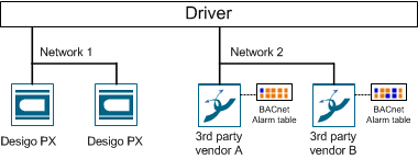
2a – Create a Network Using the Network Wizard
- Select Project > Field Networks > [BACnet network].
- Select the BACnet tab.
- Open the Network setting expander and perform the following steps:
a. Network settings: Select the communication driver from the drop-down list.
b. AutoDiscovery: If you select the Online import workflow (see below), you select the check box as per the AutoDiscovery description.
c. Hierarchy Mapping: Set the target views for the third-party BACnet file import if you do not use the network wizards.
d. Block Commands Behavior: Not used for third-party BACnet.
e. Global Objects Folder Mapping: Not used for third-party BACnet devices.
- Click Save .
- Conduct the additional steps as per Online or Offline (see below) Engineering.
2b – Manually Create Network for AutoDiscovery
To manually create a network, proceed as follows:
Create the Network
- Select Project > Field Networks > Management System > Servers > Main Server > Drivers.
- Click New , and select New BACnet driver.
- In the New object dialog box, enter a name and description.
- Click OK.
- The new driver is available in System Browser.
- Click Save .
Assign the Driver
- Select Project > Field Networks > [Network name].
- Click the BACnet tab and open the Network Setting expander.
- From the drop-down list, select the driver.
- Click Save .
Create the Views
- Select Project > System Settings > Views.
- Select the Views tab and enter the data for:
- Description (name in the Management View)
- Root description (name of the root folder)
- Root name (system name for the root folder)
- In the Type drop-down list box, select one of the following options:
‒ Customized
‒ Logical
‒ Physical
- Click Save .
- Repeat steps 2 and 3 for additional views.
- Conduct the additional steps as per Online Engineering (see below).
2c – Manually Create a Network for EDE File
Proceed as follows to manually create a network:
Create the Network
- Select Project > Field Networks > Management System > Servers > Main Server > Drivers.
- Click New , and select New BACnet driver.
- In the New object dialog box, enter a name and description.
- Click OK.
- The new driver is available in System Browser.
- Click Save .
Assign the Driver
- Select Project > Field Networks > [Network name].
- Click the BACnet tab and open the Network Setting expander.
- From the drop-down list, select the driver.
- Click Save .
Determine the Views from the Import File
Views can only be determined by importing the EDE file in the system.
- Click the Import tab.
- Click Browse and select the file for import.
- Click Open.
- In the Source Items list, click
 to select all files.
- Click Import.
- A confirmation message displays.
- Click Yes.
Create the Views
- Select Project > System Settings > Views.
- Select the Views tab and enter the data for:
- Description (name in the Management View)
- Root description (name of the root folder)
- Root name (system name for the root folder)
- In the Type drop-down list box, select one of the following options:
‒ Customized
‒ Logical
‒ Physical
- Click Save .
- Repeat steps 2 and 3 for additional views.
- Conduct the additional steps as per Online Engineering (see below).
Assign the Hierarchies
- Select Project > Field Networks > [Network name].
- Select the BACnet tab.
- Open the Hierarchies Mapping expander.
- All existing hierarchies are displayed in the Hierarchy Name column.
- In System Browser, select the new view, for example, Logical.
- An object for the selected view is displayed in System Browser.
- Drag the object to the Hierarchies expander in the Import hierarchy under this node column, of the corresponding line, for example, Logical.
- Conduct the additional steps as per Offline Engineering (see below).
The Discovery function scans the entire BACnet network for BACnet devices. We recommend using available filter criteria for the scan to avoid unnecessarily impairing the network.

Restrictions
The following restrictions apply when using online import with Discovery:
- Only standard BACnet objects are supported. Proprietary object and object extensions are lost.
- The objects are displayed alphabetically in System Browser.
Scan for Devices
The BACnet Object Browser scans a BACnet network for devices and their status.
- The PICS from the respective manufacturer support the required devices and objects.
- The network and driver are created and active.
NOTE: Logging on to Desigo CC is not necessary in this case.
- Open the Windows Start menu and select All Programs > [Vendor name] > Desigo CC > Tools > BACnet Browser.
- The BACnet Object Browser scans the network for BACnet devices.
NOTE: If multiple networks have been defined, they are not displayed using the defined network names. The designation in the BACnet Object Browser is System1_1, System1_2, System1_3, and so on.
- Select a device from the system tree in the left pane.
- The right pane is updated with all associated information on the device, sorted by property name and value column.
- For subsequent Discovery (application of a filter), note the following data:
- vendor-identifier
- object-identifier
- The device data for the online import into Desigo CC are established.
No Communication is Available | |
Possible Causes | Proceed as Follows... |
Management platform is located on the same network:
|
|
BACnet driver not working. |
|
Start a Network Scan
- You have completed the optional Scan for devices workflow and the information needed to filter is available.
- The PICS from the respective manufacturer support the required devices and objects.
- Select Project > Field Networks > [Network name] and click the Discovery tab.
- Open the Hierarchies Mapping expander.
- In System Browser, select the logical hierarchy and drag the top node to the column Import this hierarchy under this node.
- Click Save .
- Open the Discovery Settings expander.
- In the Scan timeout in seconds field, set the maximum time for scanning devices (Default: 60 seconds).
NOTE: If Enable devices auto-discovery is checked, the scanned devices are immediately imported to the project database. Use Scanning for Devices instead to avoid importing devices.
- Select the filter criterion:
- Use network filter and enter the Network number filter.
- Use instance filter and enter the Beginning instance and Ending instance (object-identifier).
- Use vendor filter and enter a Vendor ID, see the table below.
- Click Save .
- Click Scan.
- As devices are discovered, they display in the Device Discovery expander of the Network Scan section.
Vendor ID
List of Some Vendor IDs | |||||
ID | Vendor | ID | Vendor | ID | Vendor |
0 | ASHRAE | 23 | York Controls Group | 313 | Siemens Energy & Automation, Inc. |
2 | The Trane Company | 39 | Kieback & Peter GmbH & Co KG | 314 | ETM Professional Control GmbH |
5 | Johnson Controls, Inc. | 73 | ABB Gebäudetechnik AG Bereich NetServ | 329 | TROX GmbH |
7 | Siemens Switzerland Ltd (formerly: Landis & Staefa Division Europe) | 74 | KNX Association cvba | 335 | Schneider Electric |
9 | Siemens Switzerland Ltd | 80 | Fr. Sauter AG | 387 | Securiton AG |
10 | Schneider Electric | 189 | Schneider Toshiba Inverter Europe | 450 | Hitachi Ltd. |
11 | TAC | 190 | Danfoss Drives A/S | 747 | Fraport AG |
17 | Honeywell Inc. | 222 | WAGO Kontakttechnik GmbH & Co. KG |
|
|
19 | TAC AB | 226 | Phoenix Contact GmbH & Co. KG |
|
|
20 | Hewlett-Packard Company | 227 | Grundfos Management A/S |
|
|
22 | Siemens Switzerland Ltd (formerly: Cerberus AG) | 312 | Honeywell Security Deutschland, Novar GmbH |
|
|
- The vendor ID list is available at: http://www.bacnet.org/VendorID/.

NOTE:
Some suppliers, such as Siemens Ltd., have multiple Vendor IDs.
Import Data Points
- The Discovery tab is selected.
- The devices are listed in the Device Discovery expander of the Network Scan section.
- Select a device.
- Click Objects.
- All data points of that device are listed.
- Select the data points you want to import.
- Click Save .
- Click Back.
- Repeat steps 1 to 3 for each device you want to import.
- Click Import.
- The progress displays in the Discovery Status section.
- The data points display in System Browser below the selected network.
Stop the Network Scan
- Select Project > Field Networks > [Network name] and click the Discovery tab.
- Open the Discovery Settings expander.
- Clear all check boxes.
- Click Save .
- The network scan is stopped.
Assign/Change a Function
- Select Project > Field Networks > [Network] > Hardware > [Device name] > [Data point].
- Click the Object Configurator tab.
- Open the Main expander.
- In the Function drop-down list, select the corresponding function.
- Click Save .
- Repeat steps 1 to 5 for each additional data point.
Link Objects
The Discovery function imports data points to the Management View. They must be manually linked for the data points to also be available in the Logical View or User View. The following workflows use the Logical View as an example but they also apply to any other view.
Create a Hierarchy Structure
- The Logical View or User View is available.
- In System Browser, select Logical View.
- Select Logical.
- Select the Views tab.
- Select the root folder.
- Click Add Aggregator and select an object hierarchy (property, building, floor, room element).
a. In the New Object dialog box, enter a name and description.
b. Click OK.
- Repeat the process to create the required hierarchy structure.
- Click Save .
Create Related Items
- The hierarchy structure is created in the Logical View.
- In System Browser, select the Logical View.
- Select the Manual Navigation check box.
- The workspace is fixed. The view does not change when selecting the data points.
- In System Browser, select Management View.
- The System Browser is in Management View and the Views workspace displays the Logical View.
- In the Views workspace, open the corresponding hierarchy.
- In System Browser, select the object and drag it to the appropriate hierarchy of the Views workspace.
- Repeat steps 4 to 5 to create additional related items.
- Click Save .
- The objects are linked to the Logical View and can be viewed in System Browser.

- For the Logical and User View, create one configuration file (see below) each.
NOTE: No configuration files are needed if none of the two views are used.
- (Optional) In the EDE file, supplement the function to the given data points.
- Check the Import rules.
- Import the EDE data.
- Supplement the imported data points with Function (only if this is not done under Step 2).
Create/Modify Configuration Files
- Configuration files for the Logical or User View (optional) are created. The imported objects are only displayed in Management View if no configuration file is available.
- Check the delimiters in your EDE file. Open the EDE file using a text editor.
- Using a text editor, create a new Hierarchy-User.txt file or Hierarchy-Logical.txt file (see example at the end of the workflow).
NOTE: The mapping files must be in the same folder as the import files.
- (Optional) Add the correct code-page information for encoding, for example, !encoding!UTF-8.
- (Optional) In separators-1 change the default separator (;) for the EDE file according to your requirements.
- (Optional) In separators-2 change the delimiter for the State text and Unit text columns according to your requirements.
- Define the Reference column for hierarchy mapping (default column = keyname).
NOTE: If the Keyname field is empty on an object, no Logical View or User View is created for this object. The object is, however, displayed in Management View.
- Define the following entries for each used hierarchy level (for example, Location, Building, Floor and so on).:
- Hierarchy Separator for the reference column (for example, _ ' :). Required for parsing the various hierarchy levels.
- Minimum length of the corresponding hierarchy level.
- Maximum of the corresponding hierarchy level.
NOTE: For fixed field lengths, the minimum and maximum length must be the same and the hierarchy separator left out.
- (Optional) A description of the corresponding hierarchy level.
NOTE: The description text for a virtual hierarchy object is displayed in System Browser.
- Select File > Save.
- Copy the file to the folder where the EDE file is located.
Example for a Hierarchy-User.txt or Hierarchy-Logical.txt file:
!encoding!utf-8
#separators-1#;
#separators-2#,;
:column-name:keyname
,_,1,15,Location
,:,1,15,Building
,_,1,15,Floor
,_,1,20,Plant
,_,1,20,Object
,_,1,25,Data point
(Optional) Family name extension
The selected files are checked for proper syntax prior to import. If an error message is displayed, click Open Log for additional information.
If the Hierarchy-User.txt and Hierarchy-Logical.txt files are used, the minimum and maximum length of the hierarchy level of the data point is checked. An error message is displayed if it is too short or too long. The data point is created in the database, but not visible for the corresponding view.
Supplement an Excel File
- In Excel, open the EDE file (CSV or XLSX).
- Add the column name Function on the same line as the keyword Keyname.
- In the Function column, enter a unique function-key for each data point.
- Click Save.
Create a Function Key
Add the Function to the EDE file, if:
- The third-party BACnet device has a standardized data point name
- Lots of data points have the same function
- Future projects have the same data point names of the third-party BACnet device
Workflow
- Supplement function key in the EDE file.
- Extend import rules for third-party BACnet devices.
- (Optional) Export the import rules for additional projects.
- (Optional) Import the import rules to the new project.
- Select Project > System Settings > Libraries > L1 Headquarter > BA > Device > BACnet > Import rules.
- In the Import Rules tab, open the Instance Attributes Mapper expander.
- Click Add.
- A new function key line is added.
- In the Standard Feature drop-down list box, enter the Reference column text field in the EDE file (for example, FunctionKey).
- Define the FunctionKey entries based on the following example:
- Value of FunctionKey: T_SU
- Function name: Sensor
- Discipline: Building automation
- Subdiscipline: Air handling
- Type: Heating coils
- Subtype: Preheater
- Repeat steps 3 to 5 for each additional function key.
- Click Save .
- Export the created function keys.

Export a Function Key
The function keys are overwritten as part of the HQ program update.
Back up the created function keys. After the program update, the function keys must be manually imported to the main project.
- The function keys are created.
- Select Project > System Settings > Libraries > L1 Headquarter > BA > Devices > BACnet > Import rules.
- In the Import Rules tab, open the Instance Attributes Mapper expander.
- Click Export.
- In the dialog box, select a destination and enter a name.
- Click Save.
- Save the file to another medium.
Import a Function Key
After the program update, the function keys must be manually imported to the main project.
- A function key file is available.
- Select Project > System Settings > Libraries > L1 Headquarter > BA > Device > BACnet > Import rules.
- In the Import Rules tab, open the Instance Attributes Mapper expander.
- Click Import.
- Select the folder and file name.
- Click Open.
- The function keys are imported to the main project.
Import Data
- The network and BACnet driver are created and active.
- The data file includes a description for each data point. The missing description is displayed with the symbol ~.
- (Optional) Create Hierarchy-User.txt and Hierarchy-Logical.txt configuration files for the Logical View and User View.
- Select Project > Field Networks > [Field Network].
- In the Import tab, click Browse and select the EDE file.
- Click Open.
- In the Files of type drop-down list, select EDE text file (*.csv) file type or EDE Excel (*.XLSX).
NOTE: If the Hierarchy-User.txt and Hierarchy-Logical.txt files are used for mapping the views, they must be located in the same location as the import files.
- Select the desired import file.
NOTE 1: The Hierarchy-User.txt and Hierarchy-Logical.txt files cannot be selected.
NOTE 2: If an error is found while analyzing the file, a message box displays that must be confirmed by clicking OK. Click Open Log for additional Information.
- Click Open.
- In the Source Items list, click to select all files.
NOTE: If Delete unselected objects from views is activated, all automation stations and linked objects that are not located in the selected import file are deleted. The main objects must be deleted manually in Logical and Physical View as well as User View.
- Click Import.
- A message is displayed at the end of the import process that summarizes the results in a detailed log.
Assign/Change a Function
- Select Project > Field Networks > [Network] > Hardware > [Device name] > [Data point].
- Click the Object Configurator tab.
- Open the Main expander.
- In the Function drop-down list, select the corresponding function.
- Click Save .
- Repeat steps 1 to 5 for each additional data point.
If third-party BACnet devices are integrated in Desigo CC, the alarm table must be checked in accordance with the alarm priorities of the applicable vendor or adapted where applicable. The changes are made per device.

Alarm Table Standard Third-Party BACnet Device | ||
Alarm class | Alarm state | Alarm priority |
Fault | fault | not available |
Life Safety | not available | 0‒31 |
Property Safety | not available | 32‒63 |
High Priority Alarm | not available | 64‒95 |
Medium Priority Alarm | not available | 96‒127 |
Low Priority Alarm | not available | 128‒191 |
Status | not available | 192‒255 |
Alarm Table Configurations
The following figure displays how an alarm is configured in the management platform to display in the correct alarm class on the Alarm Overview bar.
Alarm Table Standard Configuration | ||
Object | Alarm Setting | Validity Info |
Object model | Default | Valid |
Device | Alarm table | Valid |
Data point instance | Default | Invalid |

Check Notification Class
In order to ensure a correct display on the Alarm Overview bar, the notification class must be properly set up in the field network. This has to happen at the individual data point as well as on the notification class (NC) object.

There are field networks that automatically calculate the notification class from the alarm function and alarm class. In this case, the notification class cannot be edited on the alarm object. Change the alarm function or alarm class to receive another notification class.
Create a New Alarm Table
- Select Project > System Settings > Libraries > L1 Headquarters > BA > Device.
- Select the desired field network.
- Select the Library Configurator tab.
- Click Customize
 .
.
- A confirmation message is displayed.
- Click OK.
- Empty folders are created on the corresponding level.
- Select Project > System Settings > Libraries > L1 Headquarters > BA > Device [Field Network Type].
- Select the desired alarm table.
- Click Save As
 .
.
- In the Save Object As dialog box, do the following:
a. Select a destination folder for the new alarm table.
b. Enter a name and description.
c. Click OK.
- The new alarm table is available in System Browser.
- Edit the alarm table as needed.
- Click Save .
Assign a New Alarm Table
- Select Project > Field Networks > [Network name] > Hardware > [Device].
- In the Object Configurator tab, open the Properties expander.
- Select the Alarm.OffNormal property or another alarm property.
- In the Alarm Configuration expander, select the Valid check box (blue is displayed).
- Select the Field System option and the corresponding Alarm Table from the drop-down list.
- (Optional) Repeat the assignment of a new alarm table for all appropriate devices.
NOTE:
If the Valid check box is displayed in gray (see the color-coded check boxes below), the library entries for the object model and function are not considered.
Inheritance Rules for Object Model, Function, and Object | ||
Icon | Color | Description |
| White | No value is inherited. |
| Gray | The project instance value is inherited. |
| Green | The function inherits the value. |
| Blue | The object model inherits the value. |
| Question mark with a yellow background. | The value is undefined until the instance is saved. |


While you change inheritance properties, you cannot disable an inheritance. As a result, the state changes from  to
to  or
or  when editing. This display for the inheritance function is used for the Main, Properties, Details, and Alarm Configuration expanders.